- 您现在的位置:买卖IC网 > Sheet目录3870 > PIC18F44K22-I/PT (Microchip Technology)IC PIC MCU 16KB FLASH 44TQFP
2010-2012 Microchip Technology Inc.
DS41412F-page 59
PIC18(L)F2X/4XK22
4.0
RESET
The PIC18(L)F2X/4XK22 devices differentiate between
various kinds of Reset:
a)
Power-on Reset (POR)
b)
MCLR Reset during normal operation
c)
MCLR Reset during power-managed modes
d)
Watchdog Timer (WDT) Reset (during
execution)
e)
Programmable Brown-out Reset (BOR)
f)
RESET
Instruction
g)
Stack Full Reset
h)
Stack Underflow Reset
This section discusses Resets generated by MCLR,
POR and BOR and covers the operation of the various
start-up timers. Stack Reset events are covered in
WDT Resets are covered in Section 24.3 “Watchdog
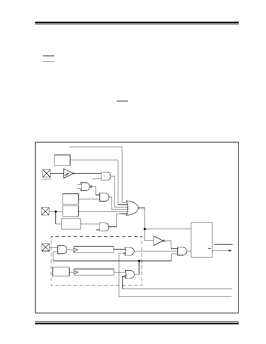
A simplified block diagram of the On-Chip Reset Circuit
is shown in Figure 4-1.
4.1
RCON Register
Device Reset events are tracked through the RCON
register (Register 4-1). The lower five bits of the
register indicate that a specific Reset event has
occurred. In most cases, these bits can only be cleared
by the event and must be set by the application after
the event. The state of these flag bits, taken together,
can be read to indicate the type of Reset that just
occurred.
This
is
described
in
more
detail
in
The RCON register also has control bits for setting
interrupt priority (IPEN) and software control of the
BOR (SBOREN). Interrupt priority is discussed in
BOR
is
covered
in
FIGURE 4-1:
SIMPLIFIED BLOCK DIAGRAM OF ON-CHIP RESET CIRCUIT
External Reset
MCLR
VDD
OSC1
WDT
Time-out
VDD
Detect
OST/PWRT
LFINTOSC
POR
OST(2)
10-bit Ripple Counter
PWRT(2)
11-bit Ripple Counter
Enable OST(1)
Enable PWRT
Note 1:
See Table 4-2 for time-out situations.
2:
Brown-out
Reset
BOREN
RESET
Instruction
Stack
Pointer
Stack Full/Underflow Reset
Sleep
( )_IDLE
1024 Cycles
65.5 ms
32
s
MCLRE
S
R
Q
Chip_Reset
发布紧急采购,3分钟左右您将得到回复。
相关PDF资料
PIC24FJ128GA110T-I/PF
IC PIC MCU FLASH 100TQFP
PIC18LF8393-I/PT
IC PIC MCU FLASH 4KX16 80TQFP
PIC16F1946-I/PT
IC MCU 8BIT FLASH 64TQFP
PIC16LF1939-I/ML
IC MCU 8BIT FLASH 44QFN
PIC18LF6493-I/PT
IC PIC MCU FLASH 8KX16 64TQFP
DSPIC33FJ64GP310T-I/PT
IC DSPIC MCU/DSP 64K 100TQFP
DSPIC33FJ64GP310T-I/PF
IC DSPIC MCU/DSP 64K 100TQFP
PIC16C622A-20I/SO
IC MCU OTP 2KX14 COMP 18SOIC
相关代理商/技术参数
PIC18F44K22T-I/ML
功能描述:8位微控制器 -MCU 16KB Flash 768B RAM 8b FamilynanoWat XLP RoHS:否 制造商:Silicon Labs 核心:8051 处理器系列:C8051F39x 数据总线宽度:8 bit 最大时钟频率:50 MHz 程序存储器大小:16 KB 数据 RAM 大小:1 KB 片上 ADC:Yes 工作电源电压:1.8 V to 3.6 V 工作温度范围:- 40 C to + 105 C 封装 / 箱体:QFN-20 安装风格:SMD/SMT
PIC18F44K22T-I/MV
功能描述:8位微控制器 -MCU 16KB FL 768b RAM8bit familynanoWatt XLP RoHS:否 制造商:Silicon Labs 核心:8051 处理器系列:C8051F39x 数据总线宽度:8 bit 最大时钟频率:50 MHz 程序存储器大小:16 KB 数据 RAM 大小:1 KB 片上 ADC:Yes 工作电源电压:1.8 V to 3.6 V 工作温度范围:- 40 C to + 105 C 封装 / 箱体:QFN-20 安装风格:SMD/SMT
PIC18F44K22T-I/PT
功能描述:8位微控制器 -MCU 16KB Flash 768B RAM 8b FamilynanoWat XLP RoHS:否 制造商:Silicon Labs 核心:8051 处理器系列:C8051F39x 数据总线宽度:8 bit 最大时钟频率:50 MHz 程序存储器大小:16 KB 数据 RAM 大小:1 KB 片上 ADC:Yes 工作电源电压:1.8 V to 3.6 V 工作温度范围:- 40 C to + 105 C 封装 / 箱体:QFN-20 安装风格:SMD/SMT
PIC18F4510-E/ML
功能描述:8位微控制器 -MCU 32KB 1536 RAM 36I/O RoHS:否 制造商:Silicon Labs 核心:8051 处理器系列:C8051F39x 数据总线宽度:8 bit 最大时钟频率:50 MHz 程序存储器大小:16 KB 数据 RAM 大小:1 KB 片上 ADC:Yes 工作电源电压:1.8 V to 3.6 V 工作温度范围:- 40 C to + 105 C 封装 / 箱体:QFN-20 安装风格:SMD/SMT
PIC18F4510-E/P
功能描述:8位微控制器 -MCU 32KB 1536 RAM 36I/O RoHS:否 制造商:Silicon Labs 核心:8051 处理器系列:C8051F39x 数据总线宽度:8 bit 最大时钟频率:50 MHz 程序存储器大小:16 KB 数据 RAM 大小:1 KB 片上 ADC:Yes 工作电源电压:1.8 V to 3.6 V 工作温度范围:- 40 C to + 105 C 封装 / 箱体:QFN-20 安装风格:SMD/SMT
PIC18F4510-E/PT
功能描述:8位微控制器 -MCU 32KB 1536 RAM 36I/O RoHS:否 制造商:Silicon Labs 核心:8051 处理器系列:C8051F39x 数据总线宽度:8 bit 最大时钟频率:50 MHz 程序存储器大小:16 KB 数据 RAM 大小:1 KB 片上 ADC:Yes 工作电源电压:1.8 V to 3.6 V 工作温度范围:- 40 C to + 105 C 封装 / 箱体:QFN-20 安装风格:SMD/SMT
PIC18F4510-I/ML
功能描述:8位微控制器 -MCU 32KB 1536 RAM 36I/O RoHS:否 制造商:Silicon Labs 核心:8051 处理器系列:C8051F39x 数据总线宽度:8 bit 最大时钟频率:50 MHz 程序存储器大小:16 KB 数据 RAM 大小:1 KB 片上 ADC:Yes 工作电源电压:1.8 V to 3.6 V 工作温度范围:- 40 C to + 105 C 封装 / 箱体:QFN-20 安装风格:SMD/SMT
PIC18F4510-I/P
功能描述:8位微控制器 -MCU 32KB 1536 RAM 36I/O RoHS:否 制造商:Silicon Labs 核心:8051 处理器系列:C8051F39x 数据总线宽度:8 bit 最大时钟频率:50 MHz 程序存储器大小:16 KB 数据 RAM 大小:1 KB 片上 ADC:Yes 工作电源电压:1.8 V to 3.6 V 工作温度范围:- 40 C to + 105 C 封装 / 箱体:QFN-20 安装风格:SMD/SMT